
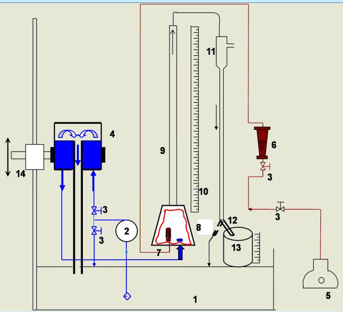
Schematic of the airlift pump system Download Scientific Diagram
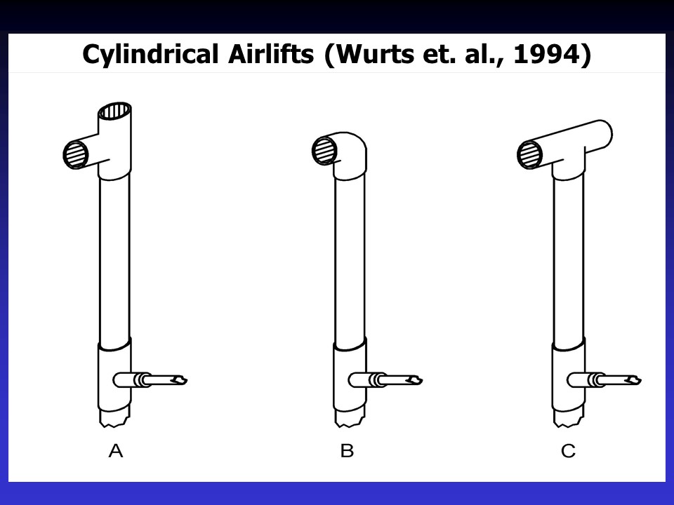
Airlift pumps have been used for sample collection of seawater (Tokar et al., 1981) as well as water circulation and aeration in aquaculture ponds (Parker and Suttle, 1987;Wurts et al, 1994).
Characteristics of an Air Lift Pump
Air lift pumps are also known as mammoth pumps, gas lifts or Löscher pumps, and are used for lifting liquids laden with solids. For this purpose a gas is injected below the liquid level, via a compressor, into the pipe, which is immersed vertically into a liquid (also see Type of pump).. The function of air lift pumps is based on the lift action of a mixture of liquid and gas (see Two-phase.

A design of an easily constructed 7.6 cm diameter airlift... Download Scientific Diagram
Get great deals from top brands for Car & Bike Accessories, Care Products & more

The designed model of the dual injection airlift pump. (Figure... Download Scientific Diagram
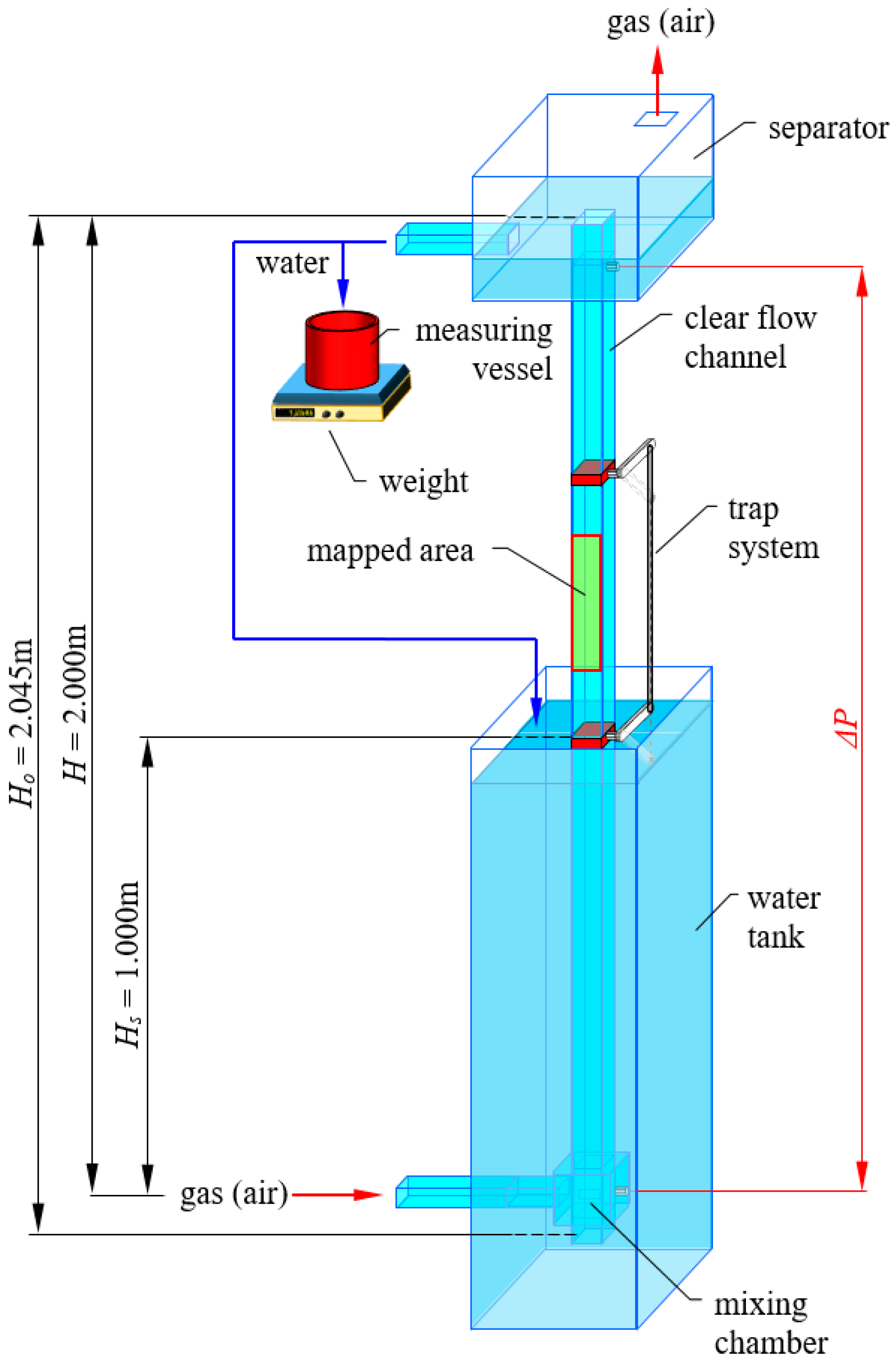
The air-lift pump is a well-established method for vertical transport of liquids and solid-liquid mixtures. The objectives of the present study are to evaluate the performance of a pump under predetermined operating conditions and to optimize the related parameters for the use of the pump for two-phase mixtures of air and water when a compressor is readily available.
Air Lift Pump momsbes
Engineered to quickly collect chips from machining. Direct flow action. Find a distributor in your area or contact us for more information about our products.
Cylindrical & Rectangular Airlift Pump Design RECTANGULAR AIRLIFT PUMPS SLIDE SHOW (JPG)
Airlift pumps, 185 cm long, were made from PVC pipe of 7.6, 10.2 and 15.2 cm inner diameters. Air was injected through a 2.5-cm pipe at 50, 65, and 80 cm below the water discharge outlet. Water.

Schematic of airlift pump with step geometry. Download Scientific Diagram
Abstract. Water flow rates were measured in airlift pumps 3·75-30 cm in diameter to develop performance data that might be useful to aquaculturists. Flows were determined when submergence of airlifts was 100% and when the center-line of the discharge was between 12·5 cm above and 5 cm below the water surface. Air was injected at 15-cm.
Air Lift Pump (Parts And Working) YouTube
This paper aims in developing a new model, referred to as the integral model, which uses a combination of a first principal approach and experimental correlations. This model can address two basic airlift design problems: Calculation of the water pumping rate for a given air flow rate, and,

Air Lift Pump (Laboratory model) YouTube
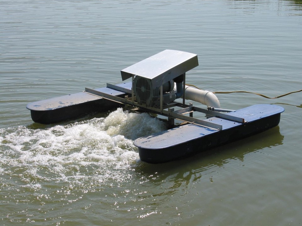
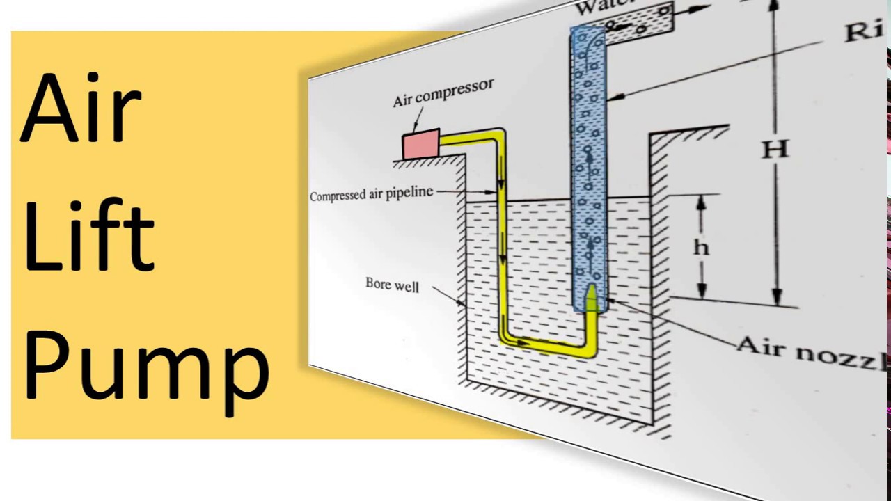
The airlift pump - also called mammoth pump - exploits the increase of the oxygen intake in water under pressure. At the same time, rising air is used to lift - and therefore circulate - water. This makes the mammoth pump suitable for aerating and circulating large volumes of water.

AirLift Pump 2 inches 3D CAD Model Library GrabCAD
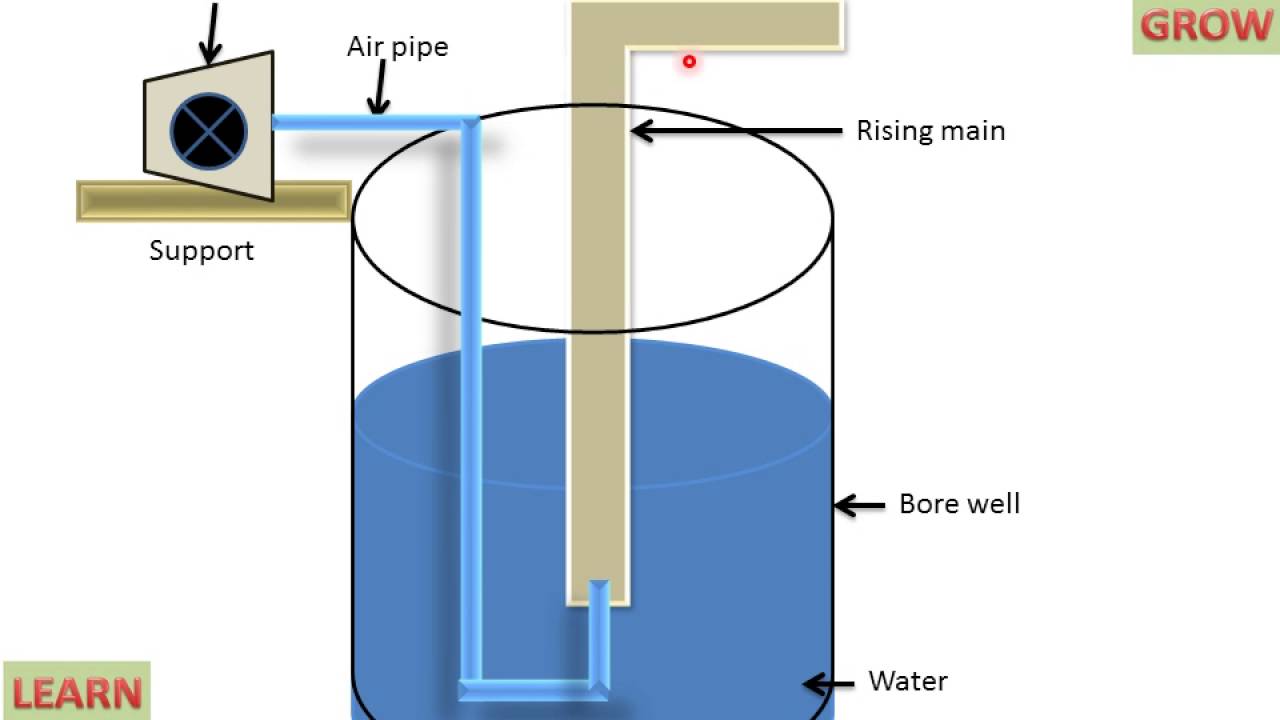
An air-lift pump is a device which is used to lift water from a well or a sump with the use of compressed air. The compressed air is made to mix with the water. It is well known that the density of water is more than the density of air.
Aquaponics Air Lift Pumps Life Empowering Technology & Science
Airlift pumps are the simplest devices used for lifting and transporting of liquid in water and wastewater systems. They constitute the subject of interest in numerous studies, focusing on their.
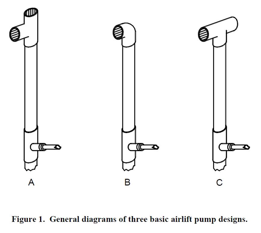
Cylindrical & Rectangular Airlift Pump Design AIRLIFT PUMPS PERFORMANCE & DESIGN
Air lift pumps are finding increasing use where pump reliability and low maintenance are required, and where corrosive, abrasive, or radioactive fluids must be handled. Although air lifts are used in nuclear fuel reprocessing plants, no general, theoretically sound equation has been proposed in the literature for tall air lift design.
Air Lift Pump YouTube
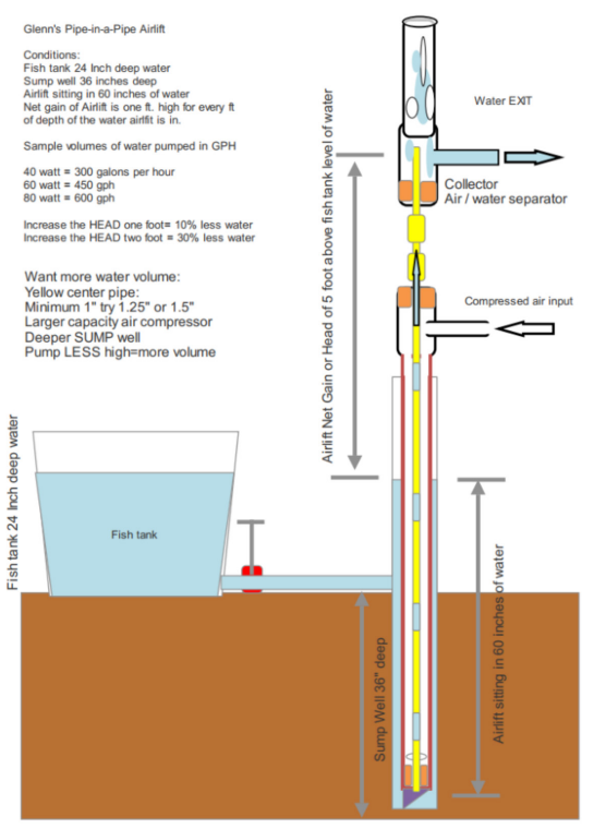
DIY Airlift Pump Design Using Plastic Pipe and Air Compressor To start, you will need to remove the well cap. If damaged, build or buy a new one. Keep the well clean. Put four holes in the well cap. (Illustration 1.) Two holes for vents, one for the 1 ¼" discharge pipe, and one for the ½ air pipe. Screen the vents.
Cylindrical & Rectangular Airlift Pump Design RECTANGULAR AIRLIFT PUMPS SLIDE SHOW (JPG)
"A General Design Equation for Air Lift Pumps Operating in Slug Flow", A.I.Ch.E. Journal, 32, No. 1, 1986 pp. 56-64. Eductors. Another way to use a motive fluid to pump another is with an eductor. Also referred to as ejectors, exhausters or siphons, the eductor's principle of operation is straightforward (see Figure 3). The motive fluid (gas or.

FloMov Airlift Pumps FloNergia
This airlift is pumping about 900 liter/hour from an IBC tank to a height of 1.8 meters to a clarifier. The vertical 3-inch PVC pipe is fed water by a 'T' connection to the IBC tank (Figure 3). This 3 inch pipe has a cap on the bottom and serves as a kind of 'sump well' for the actual 'pipe-in-a-pipe' pump.

HOW AIR LIFT PUMPS WORK YouTube
Several investigators have reported the flow rates of small-diameter airlift pumps used to lift water vertically. Spotte (1970) presented data on the vertical lift capacity of airlift "pumps 2.5-15 cm in diameter and 40-70% submerged. Spotte (1979) revised the water flow rates from his earlier edition and also included flow rates of air.